2014-02-10

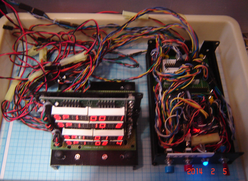
PSU 12V 5A assembly notes


PSU 12V 5A assembly notes

.END

Does the Raspberry Pi work with Windows? – Your tech questions answered - Colin Meaden

Does the Raspberry Pi work with Windows? – Your tech questions answered - Colin Meaden 2014feb09

http://www.theguardian.com/technology/2014/feb/09/your-tech-questions-answered-raspberry-pi

Do you have to use Linux with the Raspberry Pi or will Windows work with the system?

Q The Raspberry Pi is a brilliantly cheap way of getting young (and not so young) people into programming but, being Linux based, it is not to everyone's taste. Is there a low-cost equivalent – or DIY guide for sourcing components and building one – that will run Windows?

A The Raspberry Pi is an excellent little device, but it is compromised and likely to frustrate some users with its performance without some system tinkering. These limitations are arguably by design as it tries to encourage young people not to be afraid to explore what they can do with computers – this is where Linux is an excellent companion for the Pi. It makes it much easier to tinker with the core of the system or, if you get more proficient, even compile your own version of the operating system. (Compiling is when you pass in computer code, and a compiler breaks it down into the most basic instructions so that a computer processor can act on them.) Linux may not be quite as user-friendly, but it's incredibly flexible for learning and has amazing package managers to install compilers easily, as well as to install other software. This also has the benefit that, if you ruin the system, you can re-image (clear off and re-add a new version of the OS) the SD card and start again.

If you require a Windows computer, however (for example, if its primary use is going to be office tasks with some light programming), it's hard to recommend anything close to that price point. This is because Windows is a much more bloated operating system and requires higher system specifications to operate and run well. You also have to be careful that you aren't buying a Windows RT device, as you won't be able to run your own code without some more setup and, even then, you'll be limited to which languages you can write.

If you can afford the extra, and need Windows, then purchase as you would a home computer – but you'll have to be more careful with what you touch, especially if it has important files without backups.

...

Daniel is a freelance programmer for iOS and the web. He is a student and has been coding since he was eight. He is an ambassador for Young Rewired State ...

.END

2014-02-08

The Connected Home: Which Board is Right for Me? By Alasdair Allan

The Connected Home: Which Board is Right for Me? By Alasdair Allan Posted 02/07/2014

http://makezine.com/magazine/make-36-boards/which-board-is-right-for-me/


...
So, um, which board should I buy anyway?
Because of the communities that have grown up around them, I would unhesitatingly recommend an Arduino if you need an 8-bit microcontroller, or a Raspberry Pi if you need a single-board computer running Linux.
If you’re leaning toward the Pi, but worried it may not suit your application, the decision gets more complex. The Raspberry Pi is yet to become an unstoppable force, or an immovable object, like the Arduino. The most serious alternative, around the same price point, is BeagleBone Black. On the other hand, BeagleBone Black is relatively new, and its community is much smaller, so you might end up having to solve a lot of your own problems.
If you’re leaning toward an Arduino, but have specific needs (like wireless connectivity) that it doesn’t meet out of the box, then you should probably look first among the myriad of Arduino derivatives. You’ll probably find your desired feature set baked right into one of them.
Finally, if your project’s I/O requirements permit it, take a serious look at the TI LaunchPad MSP430. Its low-price, low-power requirements, and user-friendly development environment make a very strong case.

.END

2014-02-03

PSU 5V5A / 12V3A in 19" rack mount chassis


PSU 5V4A / 12V3A in 19" rack mount chassis

.END

Coocox I2C EEPROM example code reading notes 1

// *************************************************************************** 
   I2C_M_SETUP_Type transferMCfg; // I2C xmit/recv control/data structure
// *************************************************************************** 

// I2C_M_SETUP_Type;
typedef struct
{
  uint32_t sl_addr7bit; /**< Slave address in 7bit mode */
  uint8_t* tx_data; /**< Pointer to Transmit data - NULL if data transmit
                    is not used */
  uint32_t tx_length; /**< Transmit data length - 0 if data transmit
                                         is not used*/
  uint32_t tx_count; /**< Current Transmit data counter */
  uint8_t* rx_data; /**< Pointer to Receive data - NULL if data receive
 is not used */
  uint32_t rx_length; /**< Receive data length - 0 if data receive is
    not used */
  uint32_t rx_count; /**< Current Receive data counter */
  uint32_t retransmissions_max; /**< Max Re-Transmission value */
  uint32_t retransmissions_count; /**< Current Re-Transmission counter */
  uint32_t status; /**< Current status of I2C activity */
  void   (*callback)(void); /**< Pointer to Call back function when transmission complete
    used in interrupt transfer mode */
} I2C_M_SETUP_Type;


// *************************************************************************** 
   SYSCON_PeriphResetCmd(SYSCON_RSTPeriph_I2C, ENABLE);  // Enable then disable
   SYSCON_PeriphResetCmd(SYSCON_RSTPeriph_I2C, DISABLE); //   why this order?
// *************************************************************************** 

/*********************************************************************//**
 * @brief   Reset the SPI or I2C peripherals
 * @param[in]  Periph it can be
 *              - SYSCON_RSTPeriph_SSP0 : Reset SSP0
 *              - SYSCON_RSTPeriph_I2C  : Reset I2C                           
 *              - SYSCON_RSTPeriph_SSP1 : Reset SSP1
 *              NewState new state of the specified peripheral, it can be:
 *              - ENABLE  : Resets the peripheral
 *              - DISABLE : Peripheral reset de-asserted
 * @return none
 **********************************************************************/
void SYSCON_PeriphResetCmd(uint32_t Periph, FunctionalState NewState)
{
    if(NewState == ENABLE) {
        LPC_SYSCON->PRESETCTRL &= (~Periph) & 0x7;  
    } else if (NewState == DISABLE) {
        LPC_SYSCON->PRESETCTRL |= Periph & 0x7;          
    }       
}

// *************************************************************************** 
   I2C_PinsInit(I2CMODE_SF);  // Set SCL/SDA(P04/P05) mode = Standard Fast
   I2C_Init(LPC_I2C, 100000); // Set I2C peripheral clock rate = 100kHz
   I2C_Cmd(LPC_I2C, ENABLE);  // Enable I2C operation
// *************************************************************************** 

/********************************************************************//**
 * @brief Init I2C SDA and SCL pins, pins assign:
 *                I2C SCL : PIO0_4
 *                I2C SDA : PIO0_5
 * @param[in] mod, i2c mode, it can be
 *               -I2CMODE_SF  : Standard mode/ Fast-mode I2C
 *               -I2CMODE_SIO : Standard I/O functionality
 *               -I2CMODE_FP  : Fast-mode Plus I2C
 * @return None
 *********************************************************************/
void I2C_PinsInit(I2CMODE_Typedef mod)
{
    IOCON_SetPinFunc(IOCON_PIO0_4, PIO0_4_FUN_SCL);   /* I2C SCL - PIO0_4 */
    IOCON_SetPinFunc(IOCON_PIO0_5, PIO0_5_FUN_SDA);   /* I2C SDA - PIO0_5 */

    IOCON_SetI2CMode(IOCON_PIO0_4, mod);
    IOCON_SetI2CMode(IOCON_PIO0_5, mod);
}

/********************************************************************//**
 * @brief Initializes the I2Cx peripheral with specified parameter.                
 *                
 * @param[in] I2Cx I2C peripheral selected, should be LPC_I2C
 * @param[in] clockrate Target clock rate value to initialized I2C
 * peripheral
 * @return None
 *********************************************************************/
void I2C_Init(I2C_TypeDef *I2Cx, uint32_t clockrate)
{
CHECK_PARAM(PARAM_I2Cx(I2Cx));

    /* Enable I2C clock */
SYSCON_AHBPeriphClockCmd (SYSCON_AHBPeriph_I2C, ENABLE);

    /* Set clock rate */
    I2C_SetClock(I2Cx, clockrate);
    /* Set I2C operation to default */
    I2Cx->CONCLR = (I2C_I2CONCLR_AAC | I2C_I2CONCLR_STAC | I2C_I2CONCLR_I2ENC);
}


/*********************************************************************//**
 * @brief Enable or disable I2C peripheral's operation
 * @param[in] I2Cx I2C peripheral selected, LPC_I2C
 * @param[in] NewState New State of I2Cx peripheral's operation
 * @return none
 **********************************************************************/
void I2C_Cmd(I2C_TypeDef* I2Cx, FunctionalState NewState)
{
CHECK_PARAM(PARAM_FUNCTIONALSTATE(NewState));
CHECK_PARAM(PARAM_I2Cx(I2Cx));

if (NewState == ENABLE)
{
I2Cx->CONSET = I2C_I2CONSET_I2EN;
}
else
{
I2Cx->CONCLR = I2C_I2CONCLR_I2ENC;
}
}

// *************************************************************************** 
   unsigned char send_buf[10] = {0,0, 1,2,3,4,5,6,7};
   unsigned char rece_buf[10] = {0};
// *************************************************************************** 

// *************************************************************************** 
   transferMCfg.sl_addr7bit = 0xA0>>1; // Standard EEPROM 7 bit address = 1010000
   transferMCfg.tx_data = send_buf;    // Send data in send buffer 
   transferMCfg.tx_length = 8;         // Send 8 bits   
   transferMCfg.rx_data = NULL;        // Receive buffer not used 
   transferMCfg.rx_length = 0;         // Receive buffer length = 0
   transferMCfg.retransmissions_max = 3; // maximum try 3 times
   I2C_MasterTransferData(LPC_I2C, &transferMCfg, I2C_TRANSFER_POLLING); 
     // send polling mode
// *************************************************************************** 

// *************************************************************************** 
   for(i=0;i<100;i++) // Delay for EEPROM operation
   {
        for(j=0;j<1000;j++);
    }
// *************************************************************************** 

// *************************************************************************** 
   transferMCfg.tx_data = send_buf;      // Send 
   transferMCfg.tx_length = 2;           //   2 zero bits to EEPROM
   transferMCfg.rx_data = rece_buf;      // Receive
   transferMCfg.rx_length = 6;           //   6 data bits from EEPROM    
   transferMCfg.retransmissions_max = 3; // Maximum try 3 times
   I2C_MasterTransferData(LPC_I2C, &transferMCfg, I2C_TRANSFER_POLLING); 
     // receive in polling mode
// *************************************************************************** 


I2C Wikipedia reading notes

I2C - Wikipedia

I2C (Inter-Integrated Circuit, referred to as I-squared-C, I-two-C, or IIC) is a multimaster serial single-ended computer bus invented by the Philips semiconductor division, today NXP Semiconductors, and used for attaching low-speed peripherals to a motherboard, embedded system, cellphone, or other digital electronic devices.

...

SMBus, defined by Intel in 1995, is a subset of I2C that defines the protocols more strictly. One purpose of SMBus is to promote robustness and interoperability. Accordingly, modern I2C systems incorporate policies and rules from SMBus, sometimes supporting both I2C and SMBus, requiring only minimal reconfiguration.

...

I2C uses only two bidirectional open-drain lines, Serial Data Line (SDA) and Serial Clock (SCL), pulled up with resistors. Typical voltages used are +5 V or +3.3 V although systems with other voltages are permitted.

The I2C reference design has a 7-bit or a 10-bit (depending on the device used) address space. Common I2C bus speeds are the 100 kbit/s standard mode and the 10 kbit/s low-speed mode, but arbitrarily low clock frequencies are also allowed.

Recent revisions of I2C can host more nodes and run at faster speeds (400 kbit/s Fast mode, 1 Mbit/s Fast mode plus or Fm+, and 3.4 Mbit/s High Speed mode). These speeds are more widely used on embedded systems than on PCs. There are also other features, such as 16-bit addressing.

Note the bit rates are quoted for the transactions between master and slave without clock stretching or other hardware overhead. Protocol overheads include a slave address and perhaps a register address within the slave device as well as per-byte ACK/NACK bits. Thus the actual transfer rate of user data is lower than those peak bit rates alone would imply. For example, if each interaction with a slave inefficiently allows only 1 byte of data to be transferred, the data rate will be less than half the peak bit rate.

The maximum number of nodes is limited by the address space, and also by the total bus capacitance of 400 pF, which restricts practical communication distances to a few meters.

Reference design

The before mentioned reference design is a bus with a clock (SCL) and data (SDA) lines with 7-bit addressing. The bus has two roles for nodes: master and slave:

Master node — node that generates the clock and initiates communication with slaves

Slave node — node that receives the clock and responds when addressed by the master

The bus is a multi-master bus which means any number of master nodes can be present. Additionally, master and slave roles may be changed between messages (after a STOP is sent).

There are four potential modes of operation for a given bus device, although most devices only use a single role and its two modes:

master transmit — master node is sending data to a slave

master receive — master node is receiving data from a slave

slave transmit — slave node is sending data to the master

slave receive — slave node is receiving data from the master

The master is initially in master transmit mode by sending a start bit followed by the 7-bit address of the slave it wishes to communicate with, which is finally followed by a single bit representing whether it wishes to write(0) to or read(1) from the slave.

If the slave exists on the bus then it will respond with an ACK bit (active low for acknowledged) for that address. The master then continues in either transmit or receive mode (according to the read/write bit it sent), and the slave continues in its complementary mode (receive or transmit, respectively).

The address and the data bytes are sent most significant bit first. The start bit is indicated by a high-to-low transition of SDA with SCL high; the stop bit is indicated by a low-to-high transition of SDA with SCL high. All other transitions of SDA take place with SCL low.

If the master wishes to write to the slave then it repeatedly sends a byte with the slave sending an ACK bit. (In this situation, the master is in master transmit mode and the slave is in slave receive mode.)

If the master wishes to read from the slave then it repeatedly receives a byte from the slave, the master sending an ACK bit after every byte but the last one. (In this situation, the master is in master receive mode and the slave is in slave transmit mode.)

The master then either ends transmission with a stop bit, or it may send another START bit if it wishes to retain control of the bus for another transfer (a "combined message").

Message protocols

I2C defines basic types of messages, each of which begins with a START and ends with a STOP:

Single message where a master writes data to a slave;

Single message where a master reads data from a slave;

Combined messages, where a master issues at least two reads and/or writes to one or more slaves.

In a combined message, each read or write begins with a START and the slave address. After the first START in a combined message these are also called repeated START bits. Repeated START bits are not preceded by STOP bits, which is how slaves know the next transfer is part of the same message.

Any given slave will only respond to particular messages, as defined by its product documentation.
Pure I2C systems support arbitrary message structures. SMBus is restricted to nine of those structures ...

In practice, most slaves adopt request/response control models, where one or more bytes following a write command are treated as a command or address. Those bytes determine how subsequent written bytes are treated and/or how the slave responds on subsequent reads. Most SMBus operations involve single byte commands.

Messaging example: 24c32 EEPROM

One specific example is the 24c32 type EEPROM, which uses two request bytes that are called Address High and Address Low. (Accordingly, these EEPROMs are not usable by pure SMBus hosts, which only support single byte commands or addresses.)

These bytes are used to address bytes within the 32 kbit (4 kB) supported by that EEPROM; the same two byte addressing is also used by larger EEPROMs, such as 24c512 ones storing 512 kbits (64 kB).

Writing and reading data to these EEPROMs uses a simple protocol: the address is written, and then data is transferred until the end of the message. (That data transfer part of the protocol also makes trouble for SMBus, since the data bytes are not preceded by a count and more than 32 bytes can be transferred at once. I2C EEPROMs smaller than 32 kbits, such as 2 kbit 24c02 ones, are often used on SMBus with inefficient single byte data transfers.)

To write to the EEPROM, a single message is used. After the START, the master sends the chip's bus address with the direction bit clear (write), then sends the two byte address of data within the EEPROM and then sends data bytes to be written starting at that address, followed by a STOP. When writing multiple bytes, all the bytes must be in the same 32 byte page. While it is busy saving those bytes to memory, the EEPROM will not respond to further I2C requests. (That is another incompatibility with SMBus: SMBus devices must always respond to their bus addresses.)

To read starting at a particular address in the EEPROM, a combined message is used. After a START, the master first writes that chip's bus address with the direction bit clear (write) and then the two bytes of EEPROM data address. It then sends a (repeated) START and the EEPROM's bus address with the direction bit set (read). The EEPROM will then respond with the data bytes beginning at the specified EEPROM data address -— a combined message, first a write then a read. The master issues an ACK after each read byte except the last byte, and then a issues a STOP. The EEPROM increments the address after each data byte transferred; multi-byte reads can retrieve the entire contents of the EEPROM using one combined message.

Physical layer

At the physical layer, both SCL and SDA lines are of open-drain design, thus, pull-up resistors are needed. Pulling the line to ground is considered a logical zero while letting the line float is a logical one. This is used as a channel access method. High speed systems (and some others) also add a current source pull up, at least on SCL; this accommodates higher bus capacitance and enables faster rise times.

An important consequence of this is that multiple nodes may be driving the lines simultaneously. If any node is driving the line low, it will be low. Nodes that are trying to transmit a logical one (i.e. letting the line float high) can see this, and thereby know that another node is active at the same time.

When used on SCL, this is called clock stretching and gives slaves a flow control mechanism. When used on SDA, this is called arbitration and ensures there is only one transmitter at a time.

...

Clock stretching using SCL

...

Arbitration using SDA

...

Circuit interconnections

I2C is popular for interfacing peripheral circuits to prototyping systems, such as the Arduino and Raspberry Pi.

I2C does not employ a standardized connector, however, and board designers have created various wiring schemes for I2C interconnections. To minimize damage on 0.1-inch headers, some developers suggested to use alternating signal and power connections of the following wiring schemes should be used: (GND, SCL, VCC, SDA) or (VCC, SDA, GND, SCL).[4]

Buffering and multiplexing

When there are many I2C devices in a system, there can be a need to include bus buffers or multiplexers to split large bus segments into smaller ones. This can be necessary to keep the capacitance of a bus segment below the allowable value or to allow multiple devices with the same address to be separated by a multiplexer.

Many types of multiplexers and buffers exist and all must take into account the fact that I2C lines are specified to be bidirectional. Multiplexers can be implemented with analog switches which can tie one segment to another. Analog switches maintain the bidirectional nature of the lines but do not isolate the capacitance of one segment from another or provide buffering capability.

Buffers can be used to isolate capacitance on one segment from another and/or allow I2C to be sent over longer cables or traces. ...

Timing diagram

Data transfer sequence

Data transfer is initiated with the START bit (S) when SDA is pulled low while SCL stays high. Then, SDA sets the transferred bit while SCL is low (blue) and the data is sampled (received) when SCL rises (green). When the transfer is complete, a STOP bit (P) is sent by releasing the data line to allow it to be pulled up while SCL is constantly high. In order to avoid false marker detection, the level on SDA is changed on the falling edge and is captured on the rising edge of SCL.

Example of bit-banging the I2C Master protocol

...

.END